Dear All,
My 1990 Triac ATC machine works in all axis quickly, accuratley, and without hesitation. Now that I have come to programming it though the above points cannot be applied to me as an operator with the typing of individual lines of Gcode. There is no appeal whatsoever doing this particulaly since I have access to a 3D cad/cam system.
As everything works, I would prefer not to strip all the drives out and replace with Geckos etc, but simply feed the existing drives from Mach3 via a suitable interface.
I've had a good look around the site and downloaded all the relevent manuals and wiring diagrams for both the Triac and the SD drives.
Whilst previous posts, and I have read them all, suggest that this improvement to the machine is possible, they point out that Mach3 works with 5v whilst the Digiplan kit uses 24v (i think).
As not to make any of my tinkerings irreversable I would like to do the connections for mach3 through the 16 strand ribbon cable which goes from the main Triac PCB (Plug U) to the Digiplan motherboard. What I have noticed, and can be seen on the attachment, is that not all drive feeds on the 16strand cable are identified by axis. I was hoping it would say X dir, Ydir, Zdir etc but it doesn't.
As always I look forward to your input and guidance.
Thanks ...Richard
CNC Expert

Hi
Yup it's possible, for more info see the thread on my lathe-
viewtopic.php?t=452&highlight=starturn
This is the interface circuit I have used and its still working like a dream -
files/digiplan_interface_155.jpg
There are some manuals for the drivers I posted on here somewhere - probably the easiest way is to find the step pin on each drive and continuity test back over the connections in the ribbon cable
Cheers
Dave
CNC Apprentice

Thanks David & Admin,
It looks like I can make that thing shown on the link with bits picked up from ebay, in fact I could probably buy the bits to build a 100 for a couple of quid ...but:
1) what is it?
2) How does it work?
3) can I just wire it into the ribbon cable?
4) which way round does it go?
5) I guess I will need one for each axis
6) What do I do with the pins for Drive Fault, Boost, Energise, 0V, and 24V.
...and yes you re correct, I am not a graduate of electronic engineering
...Richard
CNC Expert
1) Basically it's a simple switch
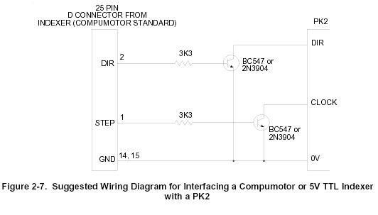
2) The signal lines on the stepper are held at a voltage (12v from memory), a change in the signal consists of hooking them up to 0v. The transistors are used as switches, the resistors are there to limit current.
3,4,6) The left hand side of the diagram is the parallel port (safer to wire this through an opto-isolator board) the right hand side is the stepper driver. If you look up the manuals for the drivers you can find the step and dir pins and hook the circuit up to them. Leave the rest of the pins alone. The only other thing you might have to mess with is the enable input.
5) yup - so that is 2 transistors and resistors per axis, should cost about 50p per axis from maplins!
My advice would be to try 1 axis first. If you look at the pics on my thread you should be able to follow some of the wiring showing how simpleit is.
Cheers
Dave
CNC Apprentice
Well it must be inflation at Zimbabwe type proportions as the toal for the parts came to £8.07 from Maplins  Still a damned site cheaper than three new Gecko drives if it works.
The green screw connectors can be wired to the breakout board and the 16pin socket will plug directly into the ribbon cable from the Digiplan motherboard.
Not very pretty I am sure you will agree, but fingers crossed though.
...Richard
The green screw connectors can be wired to the breakout board and the 16pin socket will plug directly into the ribbon cable from the Digiplan motherboard.
Not very pretty I am sure you will agree, but fingers crossed though.
...Richard
Attachments:
- DSCF1278.JPG (64.08 KiB) Viewed 34391 times
CNC Apprentice
...well that was a bit of a disaster!
I think I might have to improve my soldering skills for version 2 as I must have had a dead short on my first attempt as the 4.5v battery I made up got rather warm and nothing worked.
I guess that the 3K3 resistor on the diagram is there to limit flow of current from the computer, not to protect the transistor from damage as it seems, or should I say I was told, it is vastly oversized to be matched with the BC547.
I have made up a LED with resistor test lamp and for version 2 will test each leg of the circuit board as I build it.
Fingers crossed
...Richard
CNC Expert
Are you using a breakout board between the PC your circuit? It is a good idea to use an opto-isolated breakout board to protect the PC. Have a look at the ones here -
https://www.cnc4pc.com/Store/osc/index.php?cPath=33
From memory I didn't use the BC547 as I couldn't get any so I used a higher spec transistor instead -but the same circuit. How are you testing the operation - just with a battery or are you using software such as Mach ?
Cheers
Dave
https://www.cnc4pc.com/Store/osc/index.php?cPath=33
From memory I didn't use the BC547 as I couldn't get any so I used a higher spec transistor instead -but the same circuit. How are you testing the operation - just with a battery or are you using software such as Mach ?
Cheers
Dave

Site Admin
Can't you etch a PCB on your machine ???
That would make a nice project, and once you've done it once - you could prototype anything
If you could get hold of a gerber file, I'd be willing to run it through our new software and make a CNC file for you.
(PCB wizard you can get from Maplins fairly cheaply)
That would make a nice project, and once you've done it once - you could prototype anything
If you could get hold of a gerber file, I'd be willing to run it through our new software and make a CNC file for you.
(PCB wizard you can get from Maplins fairly cheaply)
CNC Apprentice
David
I was doing the testing with 3off AA 1.5v batteries on the computer side of the circuit, and then an LED and resistor on the machine side of the circuit which was also linked to the same battery and ground.
Don't worry, I didn't put it anywhere near the computer. At this stage I would just like to prove that I can control the PKS drives from Mach3 via your circuit. Depending on whether I can or need to refit with Geckos will depend on which breakout board I choose. I was looking at Campbell Designs board but this isn't optically isolated on the step and direction circuits as it relys on the Geckos which have opto's built in. Only the most expensive CNC4PC boards are fully opto-isolated but they have had some poor reviews on the Mach3 forum.
I have an old computer that will play guinea pig to my experiments as I realise this is the time when I really need protection from a break-out board, problem is though is that breakout boards are dearer than scrap computers!
Admin
Isn't that like the problem of how man made the first lathe ...without a lathe to make one with
Seriously though, are you offering to make me a pcb if I get you the Gerber file to generate your machine codes?
If so ...cheers
...Richard
Site Admin
I thought your machine was working now ? Your aiming for mach3 in order to get 3D and modern control software ?Isn't that like the problem of how man made the first lathe ...without a lathe to make one with
Creating the g-code for a PNC3 triac would be no problem from a Gerber file - a two minute job. Getting me to cut and make a PCB as well - thats another matter !
CNC Apprentice
Sorry, I thought you were playing my fairy godmother. I was fully expecting your next offer would be to collect the machine and do a complete refit for free ..."wake-up Richard, you're dreaming"
Yes, you are right the machine is running and I can program it via the keypad. The immediate jump to Mach3 was brought about by the overwhelming excitement about typing in individual lines of gcode. Isn't it weird how quickly things move on, and things that would have once seemed cutting edge are now painfully slow ...or is it me getting old
Appreciate your offer of generating the code from a Gerber file and will see what I can do to get hold of PCB Wizard.
Thanks ...Richard
CNC Apprentice
Hi Richard
I have a PNC Triac. I am watching your conversion as its something I plan to do so I can cut 3D etc.
Did you know if you buy Denfords QuickCAM 2D (£150 on ebay?) they have done a post for the PNC3 Triac. I use it all the time for 2.5D work. You draw up your work in CAD, produce the CNC code with it and send it to the machine with the industrial text editor. Dead simple. You can down load it free to look at.
Most of what you will do will be 2.5D anyway! It still has issues like the arch quadrants but would get you started.
Matt
CNC Expert
There is potentially one big advantage for going to geckos. From memory, all the stepper motors are rated around 3A. However, the X and Y digiplan drivers are only 2A, and the Z axis is a 3A - so potentially you may be able to get some more torque from the motors. Whether the power supply is upto it is another matter.
You also have the issue of spindle speed to look at - that may be a bigger kettle of fish !
You also have the issue of spindle speed to look at - that may be a bigger kettle of fish !
CNC Apprentice
Hi Matt,
Thanks for your reply. Whilst I appreciate what you are saying about cutting more 2.5D than 3D, I don't really know what I will use the machine for when it is done! The fun for me is seeing if I can actually get a machine, for which I paid £200, running as good as it can (3D profiles, CAD, CAM) at the lowest cost to me. My next problem will be getting the ATC working but this has to be done.
It would be easy to buy three Geckos and a breakout board and set it going but i'm a bit strange in that the easy route is never much fun ...and also i'm a tight Yorkshireman.
Once it is running though I do have plenty of 'friends' who are quite happy to keep me busy with it. Well they would as i'm doing it for nothing!Forthcoming projects include conrods for an Alvis sports car, small cams for a specialist textile testing machine, and the mold for the cowl on a model jet engine.
Regards ...Richard
CNC Apprentice
Hi David,
The Geckos are good for 7amp apparently so would offer some serious potential improvement in performance which the cast iron structure of the machine frame, and BT35 tooling, would probably cope with. Obviously maximum performance improvement would need bigger motors, which in turn might start shredding the timing belts etc ...and anyway it's all more money As speed and depth of cut is not important, developments like that can wait till I burn out a Digiplan board. If that happens I will go to Geckos as I was quoted around £300 for a brand new copy of the Digiplan.
You are right about the speed control though, being the next big kettle of fish, but thats all part of the fun and learning. Before last weekend I had never built a circuit board in my life. Ok, it didn't work but the next one will
I have been looking at the Homann ModIO serial interface which, I hope, will look after both speed control and ATC.
...Richard
The Geckos are good for 7amp apparently so would offer some serious potential improvement in performance which the cast iron structure of the machine frame, and BT35 tooling, would probably cope with. Obviously maximum performance improvement would need bigger motors, which in turn might start shredding the timing belts etc ...and anyway it's all more money
You are right about the speed control though, being the next big kettle of fish, but thats all part of the fun and learning. Before last weekend I had never built a circuit board in my life. Ok, it didn't work but the next one will
I have been looking at the Homann ModIO serial interface which, I hope, will look after both speed control and ATC.
...Richard
CNC Expert
A ModIO is probably a good option for the ATC, alternatives include getting hold of a cheap PLC, or even making your own PIC controller. Whichever solution you chose will require some programming in Mach.
For spindle speed control you probably want to look at the Digispeed XL. I thoroughly reccomend Peters products. He has always given me great service and aftercare support.
Cheers
Dave
For spindle speed control you probably want to look at the Digispeed XL. I thoroughly reccomend Peters products. He has always given me great service and aftercare support.
Cheers
Dave
CNC Apprentice
Well still no luck.
Rebuilt the interface board and tested it with LED linked to seperate supply. I then plugged it into the drive ribbon cable and turned on the drives. The drives energised and motors locked up but when I 'pulsed' 4.5v (3x 1.5v AA cells) nothing happened.
After powering down I removed the ribbon plug and left it loose, powered up the drive cards, and tried to drive the motors from the onboard controller. When I did this a fault was indicated on the screen advising 'turn drives on' which they already were.
I don't know if this suggests that the drive board is expecting an energise signal from the main board, or vice versa, but I do seem to be missing something.
I know David (Murray) mentioned that I don't need to connect up the other pins on the ribbon cable, but something is missing to allow the motors to turn.
The other pins on the ribbon cable I have been able to identify, besides X,Y,Z step and direction, and 0v, are: Fault Z, Fault, X, Fault Y, and Energise.
The Energise pin is a bit strange as according to the Digiplan user manual an external energise signal is not needed if jumper LK4 is made, which it is.
As Idon't have an oscilloscope to monitor what is happening at the pins, any (more) help would be appreciated.
Thanks ...Richard
Site Admin
Could you make up another ribbon cable exactly as the original ?
Then all you should need to do is break-out the 6 step and direction wires... possibly ....
I'm sure the original control won't know that its step and directions are not connected, but it will proove that there are other connections still required.
Then all you should need to do is break-out the 6 step and direction wires... possibly ....
I'm sure the original control won't know that its step and directions are not connected, but it will proove that there are other connections still required.