All info relating to Viceroy machines - Lathes, sharpedge, drills etc...
Moderators: Martin, Steve, Mr Magoo
-
bottleveg
- Posts: 14
- Joined: Thu 28 Feb , 2013 12:17 pm
Post
by bottleveg » Sun 03 Mar , 2013 0:58 am
Hello all,
I’m new to the forum and new to lathes.
I’ve recently acquired a Viceroy 280vs (the type with the joy stick) and I need a few parts. A gear carrier and some gears are missing and the left lower nylon gear inside the headstock has sheared all it’s teeth on the one side.
Does anyone have a ‘parts machine’ or know where I can get these bits?
Also are these gears common to the whole range or do I need to look for a specific type?
The rest of the lathe seems in good condition, and is complete with all it’s original extras, so I’d like to preserve it.
Many thanks, Mark.
-
Pete.
- CNC Expert

- Posts: 284
- Joined: Wed 07 Jan , 2009 9:46 am
- Location: Kent, U.K.
Post
by Pete. » Mon 04 Mar , 2013 13:37 pm
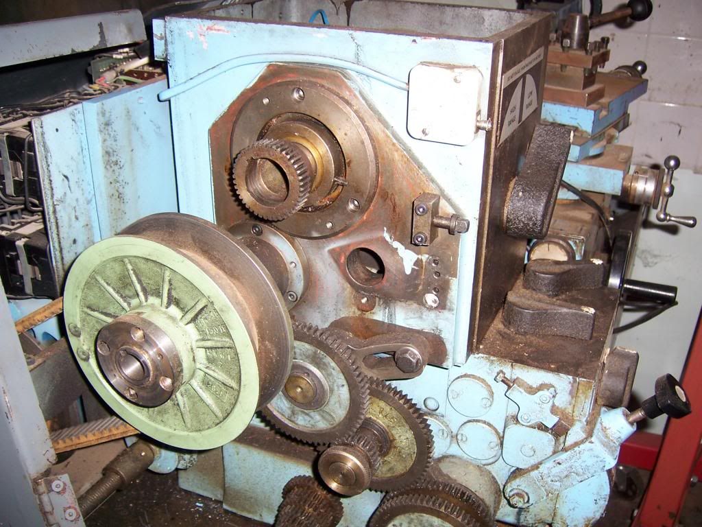
That part you are missing is the tumbler reverse, it should have four gears mounted to it. It's probably been removed because the hardened spigot it rides on (also missing) has a ruined thread. Mine has a ratty thread because someone forced a metric nut onto it though I rescued mine by making a brass nut with the proper thread and there's no real load on it.
See that small cluster of gears fixed to the casing below the pulley - one of them is probably missing, it would have been on that tumbler when it was lost. They are lettered A-G, looks like you are missing the second largest.
here is what you should have:
-
Attachments
-

- endcluster.jpg (225.33 KiB) Viewed 19877 times
-
Andy B
- CNC Guru

- Posts: 396
- Joined: Mon 20 Nov , 2006 18:19 pm
- Hardware/Software: 280 VS lathe, Denford Senior E-type mill, Senior Major Universal Mill
- Location: East Midlands, UK
Post
by Andy B » Mon 04 Mar , 2013 15:28 pm
Admin - can you move this post into the Viceroy section?
Mark - I think the tumbler gears themselves may be common to many Viceroy lathes (5" & 5 1/2"), but the arm they mounted on was specific to the 280 series.
I think you should find parts lists and drawings on here somewhere.
Parts with 'ML' numbers were carried over from the earlier 5" machines.
Parts with 'MVS' and 'BVS' will be specific to the 280 series.
Hope this helps for starters.
Andy
-
bottleveg
- Posts: 14
- Joined: Thu 28 Feb , 2013 12:17 pm
Post
by bottleveg » Tue 05 Mar , 2013 1:08 am
Pete. wrote:That part you are missing is the tumbler reverse, it should have four gears mounted to it. It's probably been removed because the hardened spigot it rides on (also missing) has a ruined thread. Mine has a ratty thread because someone forced a metric nut onto it though I rescued mine by making a brass nut with the proper thread and there's no real load on it.
See that small cluster of gears fixed to the casing below the pulley - one of them is probably missing, it would have been on that tumbler when it was lost. They are lettered A-G, looks like you are missing the second largest.
here is what you should have:
Hi Pete, thank you for your reply. This lathe came from a school and I believe the missing gears where removed when an attempt was started to replace one of the damaged nylon gears. Sadly this job was never completed and took place a couple of years ago.
The ‘small cluster of gears’ is that the set secured with a wing nut? I’ll check to see if I have a full set.
Mark.
-
bottleveg
- Posts: 14
- Joined: Thu 28 Feb , 2013 12:17 pm
Post
by bottleveg » Tue 05 Mar , 2013 1:17 am
Andy B wrote:Admin - can you move this post into the Viceroy section?
Mark - I think the tumbler gears themselves may be common to many Viceroy lathes (5" & 5 1/2"), but the arm they mounted on was specific to the 280 series.
I think you should find parts lists and drawings on here somewhere.
Parts with 'ML' numbers were carried over from the earlier 5" machines.
Parts with 'MVS' and 'BVS' will be specific to the 280 series.
Hope this helps for starters.
Andy
Hi Andy,
Sorry if I’ve posted in the wrong place!
Would you know if the nylon gears are reversable?
If all else fails, I’m wondering if I could take the damaged gear out and replace it the other way round. That should (?) allow me to use the machine as a lathe until I, hopefully, find the parts needed.
Mark.
-
Pete.
- CNC Expert
- Posts: 284
- Joined: Wed 07 Jan , 2009 9:46 am
- Location: Kent, U.K.
Post
by Pete. » Tue 05 Mar , 2013 2:01 am
You cannot reverse the nylon gear. What is the tooth count of the one that's damaged? I have a spare gear here, it's the one that doesn't slide with the lever. Since one side is stripped on yours I suspect the one you need is the one that DOES slide.
-
bottleveg
- Posts: 14
- Joined: Thu 28 Feb , 2013 12:17 pm
Post
by bottleveg » Tue 05 Mar , 2013 20:43 pm
Pete. wrote:You cannot reverse the nylon gear. What is the tooth count of the one that's damaged? I have a spare gear here, it's the one that doesn't slide with the lever. Since one side is stripped on yours I suspect the one you need is the one that DOES slide.
Hi Pete,
I do indeed have the D gear missing.
My damaged nylon gear is the one that slides, but thanks for the offer of your spare.
I’ll check the tooth count at the weekend.
Thank you for your help. I’m slowly building up a picture of what’s needed.
Mark.
-
bottleveg
- Posts: 14
- Joined: Thu 28 Feb , 2013 12:17 pm
Post
by bottleveg » Sat 30 Mar , 2013 19:09 pm
I’ve done a tooth count on the nylon gear and I get it to 65, does this sound right?
Mark.
-
Pete.
- CNC Expert
- Posts: 284
- Joined: Wed 07 Jan , 2009 9:46 am
- Location: Kent, U.K.
Post
by Pete. » Sun 31 Mar , 2013 14:42 pm
Yeah 65 is the one that strips from changing the high/low speed with the spindle turning. I've made three so far but have no stock left to make any more.
-
bottleveg
- Posts: 14
- Joined: Thu 28 Feb , 2013 12:17 pm
Post
by bottleveg » Mon 01 Apr , 2013 20:02 pm
Pete. wrote:Yeah 65 is the one that strips from changing the high/low speed with the spindle turning. I've made three so far but have no stock left to make any more.
Thanks for confirming that Pete. It’s a shame you have none left but I’ll put an ad in the classified section.
One other thing, I’m having a problem downloading the parts list off here. I can only get three pages. Would it be possible for you to email it to me?
Many thanks, Mark.
-
bottleveg
- Posts: 14
- Joined: Thu 28 Feb , 2013 12:17 pm
Post
by bottleveg » Sat 07 Nov , 2015 19:19 pm
I've finally had some time to have a look at my lathe and, apart from the missing gears, it looks like I have an
electrical problem. If I put power to it I get nothing on the display. All 3 phases are live and I have a good earth.
I've bypassed the two safety micro switches (1 on the door and 1 on the rear cover) are there any more?
If I manually operate the breaker C1 it stays in, the lathe works and the display lights up.
I'm sure I'm missing something simple but without a wiring diagram I'm a bit stuck.
Any pointers?
Mark.
-
rpwilson
- CNC Expert
- Posts: 156
- Joined: Tue 03 Jun , 2014 15:20 pm
- Hardware/Software: None. I own a pre CNC Denford 280 Synchro lathe.
Post
by rpwilson » Sat 07 Nov , 2015 20:36 pm
Hi
I've got 2 copies of the wiring diagram for a 3 phase 280VS, one marked 'Prior to 8/1/79' and the other 'Revision 1 8/1/79'
Other than knowing from a photo on the
www.lathes.co.uk website that machine no. 30393 was made in April 1982, I've got no idea on how to tell when a particular machine was made.I'm guessing that they made about 1000 machines a year, so Jan 1979 would be machine No 27000 or thereabouts, but that is pure guesswork.Anyway, I'm happy to scan these diagrams and send them in if that would be any use. Beyond that, I can't help, because mine's the non joystick model.
-
bottleveg
- Posts: 14
- Joined: Thu 28 Feb , 2013 12:17 pm
Post
by bottleveg » Sun 08 Nov , 2015 11:29 am
Hi, many thanks for your reply! Mine is the joy stick model and, I think, a later model.
A scan of the wiring diagram posted on here would be very helpful.
Mark.
-
rpwilson
- CNC Expert
- Posts: 156
- Joined: Tue 03 Jun , 2014 15:20 pm
- Hardware/Software: None. I own a pre CNC Denford 280 Synchro lathe.
Post
by rpwilson » Sun 08 Nov , 2015 16:46 pm
OK, if I've got it right, here are the wiring diagrams for the 280 Synchro (non-joystick),(SK633) and the 280VS (joystick) pre and post Jan 1978. (SK601 and SK601A) I don't understand these things, so can be no help in interpreting them or aiding in fault finding. Thats one of the reasons I was happy to get a 280 Synchro - much less complex wiring/control systems. It appears from the drawing that the wiring diagram for the 280 Synchro also applies to the 5" lathe of the time
Hope it helps. By the way, did you ever source parts for the plastic drive gear and the missing tumbler gear assembly?
Richard
-
Attachments
-
- IMG_20151108_0001.pdf
- (692.11 KiB) Downloaded 897 times
-
- IMG_20151108_0002.pdf
- (637.72 KiB) Downloaded 818 times
-
- IMG_20151108_0003.pdf
- (497.56 KiB) Downloaded 794 times
-
bottleveg
- Posts: 14
- Joined: Thu 28 Feb , 2013 12:17 pm
Post
by bottleveg » Sun 08 Nov , 2015 22:14 pm
Many thanks for those Richard. You may have saved the day!
I've downloaded them and will study later.
Mark.
-
bottleveg
- Posts: 14
- Joined: Thu 28 Feb , 2013 12:17 pm
Post
by bottleveg » Mon 09 Nov , 2015 11:26 am
Well that was an easy fix! I had the phase wires round the wrong way

I now have a functioning machine, with digital display, but just a row of 0000.
Could this be a faulty hall sensor I've read about? The joy stick operates the motor screw but no change in display
I'm still looking for the above parts. I can get the machine to run happily in Low and I can get High if I don't
move the lever fully to the right, but I'd prefer to have it running correctly.
Mark.
-
rpwilson
- CNC Expert
- Posts: 156
- Joined: Tue 03 Jun , 2014 15:20 pm
- Hardware/Software: None. I own a pre CNC Denford 280 Synchro lathe.
Post
by rpwilson » Mon 09 Nov , 2015 16:03 pm
I thought I'd seen the wiring diagrams posted on here before, but couldn't find them. Today, looking for something else, I did find them! Look under 280 VS and Synchro drawings, and in the last post, there they are, plus some other wiring stuff I didn't have.
Anyway, I've got a 12 DP 20PA No. 2 gear cutter which will do 55T-135T, so could do the plastic headstock gears if theres any demand. Anybody any suggestions regarding a suitable spec and source for the material?
Richard
-
Pete.
- CNC Expert
- Posts: 284
- Joined: Wed 07 Jan , 2009 9:46 am
- Location: Kent, U.K.
Post
by Pete. » Sun 29 Nov , 2015 21:46 pm
I made some from Delrin Acetal. Seems to have worked well mine are still going strong. I do say however that you should reduce the OD of the gear slightly perhaps 10 thou even from the revised drawing (revised to change the OD/PCD) to stop the gears meshing too tightly when they heat up at high speed.