Page 1 of 1
Easiturn Mach3 Conversion Blog
Posted: Tue 07 Oct , 2008 14:54 pm
by SimonRafferty
A couple of months ago, I bought an Easiturn lathe on eBay. It works perfectly - and has executed some beautiful machining since then. However I've been frustrated by the PNC3 controller. I guess in the 1980's - it was marvelous, but these days the user interface seems very clumsy. The program entry / editing is dreadful and within a week of buying it, I had run out of space in it's memory on a single job/program.
It does have an RS232 port which talks happily to the Denford DOS software - but the editing on that is barely better than the PNC. All I've used it for is saving programs as the micro cassette drive is bust. It's a shame it cannot save tool offsets.
The only conclusion was to convert it to Mach3 - which is pretty easy to use and offers pretty decent CAM integration.
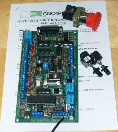
I bought a break-out-board (BOB) from CNC4PC which is fully opto-isolated and includes a 0-10v analogue output to control the spindle.
Since the drives in the PNC3 work perfectly - there seemed little point in replacing them. I decided to replace the keyboard, CPU and interface boards with the BOB + a PC with the BOB housed in the original control box.
To save a bit of cable tracing - and to give me a fall-back position if the conversion does not work - I'm going to interface to the original plugs in the PNC3.
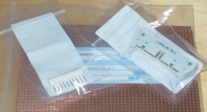
The plugs/sockets are all available from Rapid Electronics individually. Most other suppliers insist on you buying in multiples of 5 or more.
I bought a square of strip-board on which to build the interface - only because it's easy. (and nobody will be able to see it!)
Later on, I'll post a complete parts list with item numbers.
I wanted to add a Manual Pulse Generator (MPG) for using the lathe in a semi-manual mode. This is useful for simple jobs like facing off a bar without writing code. The pendant controls I found were nice - but mucho expensive! I found some Bourne rotary encoders on eBay for £10 each - so bought a couple. These will control X & Z directly via Mach.
The BOB doesn't have sufficient inputs for two MPG's - so I bought a cheap Parallel card for the PC just for that.
Last night - I traced all the connections to the plugs inside the PNC - and discovered I needed a few more sockets for my interface board. I connected up the X & Z step & direction to the BOB - and they moved! I used the same circuit that several other people have posted to convert the 5v output of the CNC4PC to the 12v input of the drives.
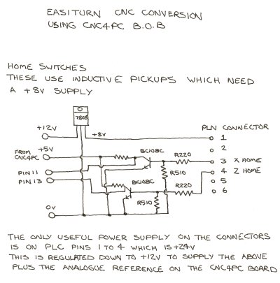
The Over-travel switches appear to be mechanical - so easy just to connect to the BOB. The home sensors however are an inductive pickup which need a simple transistor amplifier to convert to Logic levels. I stole the circuit from the Denford Manual:
I'll try it out when the connectors arrive - and let you know how it goes!
Si
Posted: Thu 09 Oct , 2008 12:07 pm
by Denford Admin
Hope you don't mind, but I've moved this to User Stories/Projects - you could keep adding to this thread then as you progress...and it won't get lost among all the general machine questions.
Posted: Sun 26 Oct , 2008 21:37 pm
by Roy
Hi Simon,
how did you get on with wiring the o/t and datum switches into the breakout board. It is somthing i need to figure out for the Triac, although i am yet to get that far, as i am struggaling with the spindle at the moment!
Posted: Mon 27 Oct , 2008 10:28 am
by SimonRafferty
I actually have the whole thing up & running nicely now. I was waiting until I get a chance to make up a new front panel before I post the rest of the conversion details.
The Home switches were inductive and needed an 8 volt supply - so used a 7808 voltage regulator.
It turned out that the built in 24v supply was too noisy. I had regulated it down to 12v (for the spindle reference) and 8v for the home switches - but both were all over the place. I used a 24v regulated supply (from eBay) instead and it sorted the whole thing out.
I wound up copying the original circuit for reading the home switches - a single transistor acting as an amplifier which 'pulls down' an input from 5v to (almost) 0v. Same sort of thing as the drivers for the stepper boards with slightly different values.
What problems are you suffering with the spindle?
Si
Posted: Mon 27 Oct , 2008 14:23 pm
by Roy
The problems i am having with the spindle is how exactly to wire it to the c11 breakout board.
My spindle is a 'Brown and pestell' inverter
and has the following wires:
1. Ref 0-10v
2. Spindle on
3. Spindle on Com
4. Spindle fwd
5. spindle com
6. spindle rev
7. ov
8. +12v
I think i am ok with 1, 7, and 8 as they seem pretty self evident. 1 to the 0-10v on bob, and 7 & 8 for the 12v supply required
But do i put the ov to the anolouge output gnd or the 12v gnd. Also there dosent seem to be a com on the c11's relays only a v_in, so do i connect both of my ''com's to this??
Also trying to find where to get the 5v from on the triac to power the board.?
Roy
Posted: Mon 27 Oct , 2008 17:26 pm
by SimonRafferty
Ah! You have very similar pin-outs to me!
Connect 2 & 3 together to make the spindle run
Connect 4 & 5 to run forward or 5 & 6 to reverse (but not both at the same time!).
Mach has one output for run forward and another for run back. I didn't use the spindle relay on the breakout board as it was wired in a contrary way!
Use one double pole relay to switch between Fwd & Rev (reverse when the relay is energised) and another to drive the spindle. Mach will only switch one or the other output for forward or reverse but you need the spindle relay on it's own for Fwd and with the reverse relay for reverse.
I connected a diode (which is just a non-return valve in water flow terms) from each of the Fwd and Rev BOB outputs and connected the other end to the coil of the spindle ON relay. (the other coil terminal to 0v).
The spindle reverse output connects directly to the reverse relay.
The diodes allow current to flow through the Rev relay if either the Fwd or Rev outputs are high, but stops current flowing back to the rev output when the Fwd output is high.
The BOB will drive a small relay with a 5v coil without any driver.
I've used a USB port on the PC to provide 5v - but you could use a 7805 voltage regulator connected to your 12v line to regulate it down.
Si
Posted: Mon 27 Oct , 2008 20:39 pm
by Roy
simon,
Thanks for that, I shall have a look into it.
I also asked the question on the Mach 3 forum, what do you think of these comments?
https://www.machsupport.com/forum/index. ... 265.0.html
I think I can do what you suggest with the 5v, My board requires 2 - 5v supplies, one on the pc side which i power via usb, and then a separate one for the outputs. Is this the same as yours, as i note you have the C11T, where as i am using the C11
Cheers Roy
Posted: Mon 27 Oct , 2008 21:15 pm
by SimonRafferty
The post
https://www.machsupport.com/forum/index. ... l#msg56921 from JimPinder is exactly what I proposed - and works.
I'd ignore the rest!
On my board, the outputs are supplied with 5v from the main USB derived supply - which drive relays etc.
Separate 5v supply is not a problem. Your mill will have an internal 24v and/or 12v supply. You can either use this plus a regulator to give you 5v or buy a regulated 5v PSU. You could even use any old PC power supply. They produce +12v -12v 0v and +5v. Use the +12v for the spindle reference and 5v for the output line supply. Connect the 0v to the 0v line on the BOB.
I can see I'll have to spend some time writing this up!
Si
Posted: Tue 28 Oct , 2008 0:33 am
by Roy
Hi simon,
sorry i must appologise, in reading your post i was a little confused by what you had done with the spindle, I first thought it was different to the 'jimpinder' post. But now i understand what you did.
Well i got it wired up tonight, I just connected wires 4,5 together, since I am not likely to ever need reverse on this machine, (not suitable for tapping or the like!) Then just the 'spindle on' and com to one relay + the 12v, gnd, and 0-10v to their appropriate terminals.
Worked first time!!

Couple of pics below of the boards wiring so far.
You seem to understand this conversion stuff pretty well simon, I think your impending write up will be invaluable to others on here. I am no electronics whizz, I am just trying to understand what others have done, and hopefully make mine work!!
Cheers Roy,
Ps. I will probably be picking your brains some more on the O/T and home switches!
Posted: Tue 28 Oct , 2008 12:57 pm
by SimonRafferty
That looks pretty good!
I'm no expert on CNC conversions - just have a little bit of general engineering experience and am not afraid of 'suck it and see' type solutions.
I was a bit afraid of something letting the smoke out - but it all seemed to stay tightly inside.
One tool I have which proved invaluable is an RF cable tracer - a bit like the one at the bottom of this page:
https://www.ashcomms.com/acatalog/Cable_Tracers.html. It injects a signal into one end of a wire which is picked up by the wand at the other when it gets close to the wire. It meant that I could trace a cable which passes through several connectors in the machine (changing colour along the way) to the appropriate terminal on the plug on my board. Probably saved hours of fiddling!
Si
Posted: Wed 29 Oct , 2008 13:42 pm
by Roy
Hi simon,
I think i have sort of figured out the homing switches, But what is the value of the other 2 resistors on your diagram?
You say you pinched the basis of this from your denford manual. Is it almost exaclty the same as in manual?
Just wondering as I have looked at the similar circuit in my triac manual, and notice it has one less resistor and an added capacitor + different resister values.
At the moment I am unsure which circuit to go with!
Thanks, Roy
Posted: Thu 05 Feb , 2009 15:24 pm
by SimonRafferty
I must get around to writing this up properly - we've just been overwhelmed with work and not had a moment!
I've been using the lathe with Mach3Turn for a while now and on the whole it's been pretty good.
A couple of things I've found which may be of use to people:
1 Use a transformer based PSU for the spindle speed controller. Switch-mode supplies often 'float' such that the low voltage -ve output is at a higher voltage than earth. Inevitably there is some earth coupling through the controllers and this, worst case can blow the 10v generator circuit (wonder how I know). I'm now using a cheap plug in transformer - and it works perfectly.
2 The spindle encoder.
Mach says this can have as many 'holes' as you like, with one wider one for the index point. However, if you have more than one, it confuses the hell out of it and it doesn't work.
Also, it requires a positive going pulse, once per revolution. If you set it up so that it's normally high and pulses to 0v, then invert it in the software - it doesn't work!
Initially, I was using an inductive pickup which had a TTL (5v) output. This proved noisy around the state transitions causing mach to mis-read sometimes. It managed to muck up most threading operations.
I replaced it with an optical pickup from CNC4PC
https://www.cnc4pc.com/Store/osc/product ... cts_id=129 with a slotted opto detector (much like the original Denford item - and it works perfectly. Nice threads!
3 Lastly, Mach itself!
Beware pausing and re-starting programs in the middle! Sometimes it has a bit of a wobbly and forgets the offsets currently in use. It seems to remember them again on the second G01 / G00 move it makes - but often that's too late and the job / tool / chuck are ruined! Likewise re-starting (using 'from here') on a tool change - sometimes it forgets the offsets for the new tool even though the tool number is displayed correctly.
I've found a few references to this on the Mach forum - but nothing very concrete as a solution and I don't think it affects everybody. A lot of people say to make the first move an 'air cut' just in case.
Si
Re: Easiturn Mach3 Conversion Blog
Posted: Wed 06 Oct , 2010 9:54 am
by SimonRafferty
I've been using the lathe with mach for a couple of years now - and it's brilliant!
The problem I had above is easily sorted - there is a setting in the general config screen (bottom left of the screen) which is something like "Forget offsets on program end" (and ruin next job when you forget it's forgotten). It defaults to being set for some reason. There were a few other niggles, but these have been sorted in newer releases of the software.
I would strongly recommend a Mach3 conversion to all of you. It has turned a decent lathe with a terrible controller into a state of the art, reliable and easy to use machine.
Since the conversion I have used it almost every day and love it!
My machine came with one of the 8 position tool-changers which someone 'hard of thinking' had tried to repair in the past. It was missing the electronics and the slotted wheel which feeds back tool number. Also the motor which actually changes the tool was toast - mechanically it's fine though!
I have adapted a small Stepper motor to turn the tool changer and have an inductive 'index pulse' which indicates when tool 1 is passing. I have a little Mach3 Macro in development which turns the stepper (fast) until it gets an index pulse, then carries on until the selected tool is in position, then backs up 1/16 of a revolution. Inside the toolchanger, there is a sort of pawl/ratchet system which locks when you reverse the drive motor and holds the tool very rigidly.
Several people have now written macros to drive the original toolchanger from Mach3, so my adaption was only necessary to fix a broken one.
I have just finished Mach3 converting a Bridgeport Interact CNC Mill - again it has transformed it into a much more usable machine. I sold the original servo drives on eBay for more than the entire conversion including new servo drives cost!
Si
Si
Re: Easiturn Mach3 Conversion Blog
Posted: Wed 06 Oct , 2010 11:14 am
by Denford Admin
What control did the Bridgeport have on it ?
I guess even if it was a decent Heidenhain variant, it's still very old, slow and low on memory compared to any PC
I'm interested to know how well Mach works with real servo machines - I presume it controls the drives through Step and Direction signals and assumes the axes are doing what they're supposed to (and not lagging behind)
Re: Easiturn Mach3 Conversion Blog
Posted: Wed 06 Oct , 2010 11:59 am
by SimonRafferty
It had a Heidenhain 370 controller with enough memory for about 3000 lines of code. Some people like the Heidenhain Conversational mode programming - but I found it pretty clunky and easier to code jobs directly in G Code.
I use SolidCam - but had to be quite careful about program sizes and chop jobs up into little chunks to fit into the memory. Although it was supposed to be able to stream G-Code, the Heidenhain PC Software to do this (it used a funny protocol for comms) refused to play along.
The motivation for the change was one of the Control Techniques Midi Maestro servo drives letting the smoke out. Despite being a 1994 machine, these are simply not available any more! I had two working drives left and sold these for more than the cost of the conversion!
I used Dugong Servo Drives
https://www.shop.cncdrive.com/index.php?productID=166 plus their break-out board
https://www.shop.cncdrive.com/index.php?productID=175 and a Smoothstepper motion controller
https://www.shop.cncdrive.com/index.php?productID=156 which allowed me to run Mach3 on a laptop without parallel ports.
The Dugong drives were easy to set up and have similar specification in terms of voltage and current to the original drives. I used the original servo motors but changed the encoders to AMT102's from Digikey which give up to 2048 pulses per rev giving an accuracy of 0.0012mm.
The servo drives use step & direction like a stepper motor. However, because they use the rotary encoders, they ramp up the current and keep trying until they achieve the demand position. You have to reduce the max speed Mach3 is sending new commands below the max that the dugongs can achieve - but this is still way faster than the 370 could manage. I'm running rapids at about 5000 mm/min. They could go a bit faster - but this is safe and beats the previous 3000.
If you over drove the old servo drives big, deep cuts in steel and high feed rates - there would be a pop and smoke coming out of the control cabinet. Now, if I over drive them - a yellow LED lights up on the Dugong saying over-current & it trips the e-stop. You push the reset button, reduce the feed rate and resume the program - no drama, no expense.
I've now added a current monitor to the spindle controller (it was built in, just never wired up by Bridgeport) and tend to use this to adjust the max feed rate as it gives a good indication of how much resistance the mill is 'feeling'.
I wrote it up on the Mach Forum here:
https://www.machsupport.com/forum/index. ... ic=15757.0
Si
Re: Easiturn Mach3 Conversion Blog
Posted: Wed 06 Oct , 2010 20:52 pm
by djc
Denford Admin wrote:I'm interested to know how well Mach works with real servo machines - I presume it controls the drives through Step and Direction signals and assumes the axes are doing what they're supposed to (and not lagging behind)
Yes and yes. You need S&D capable servos with Mach. Mach is open loop, so in broad terms, the best you can do is to wire the servo drive's error output into one of Mach's inputs.
There are numerous surplus servos now available which meet this requirement inter alia Yaskawa, Mitsubishi, Samsung.
One nice thing that can be done is to have a (1kW+) servo as your spindle drive. On the Mitsu. drives, a logic level switch on one input will change it from S&D mode (i.e. a C-axis) to analogue speed mode.
The biggest problem now is the parallel port itself as it is limited to 100kHz (IIRC). With the large number of pulses per rev. of a typical servo, and the need to run them at high speed (2k rpm), you have to use the internal gearing of the servo drive to trade off resolution for speed.
With an external motion controller (there's one called kflop that looks tasty), this problem is overcome, but at some point the cost starts approaching that of true closed loop retrofit systems.
Re: Easiturn Mach3 Conversion Blog
Posted: Wed 06 Oct , 2010 21:13 pm
by SimonRafferty
djc wrote:
With an external motion controller (there's one called kflop that looks tasty), this problem is overcome, but at some point the cost starts approaching that of true closed loop retrofit systems.
I've used a Smoothstepper motion controller - which is pretty good and only £159.
It has a couple of annoying quirks - but represents good value!
Si
Re: Easiturn Mach3 Conversion Blog
Posted: Wed 24 Nov , 2010 1:00 am
by Multispool
Simon, (or anyone)
Just starting on the home sensors pcb, can you remember the collector resistor values you used
Re pic at the beginning of this thread?
My Triac came with no boards so a bit in the dark!
Attached is what I think should be the full circuit for one home sensor, can you please confirm?
Thanks for any help...